- 您现在的位置:买卖IC网 > Sheet目录311 > AS5140 PB (ams)BOARD PROGRAM AS5140
�� �
�
�AS5140H�
�Data� Sheet� -� E� l� e� c� t� r� i� c� a� l� C� h� a� r� a� c� t� e� r� i� s� t� i� c� s�
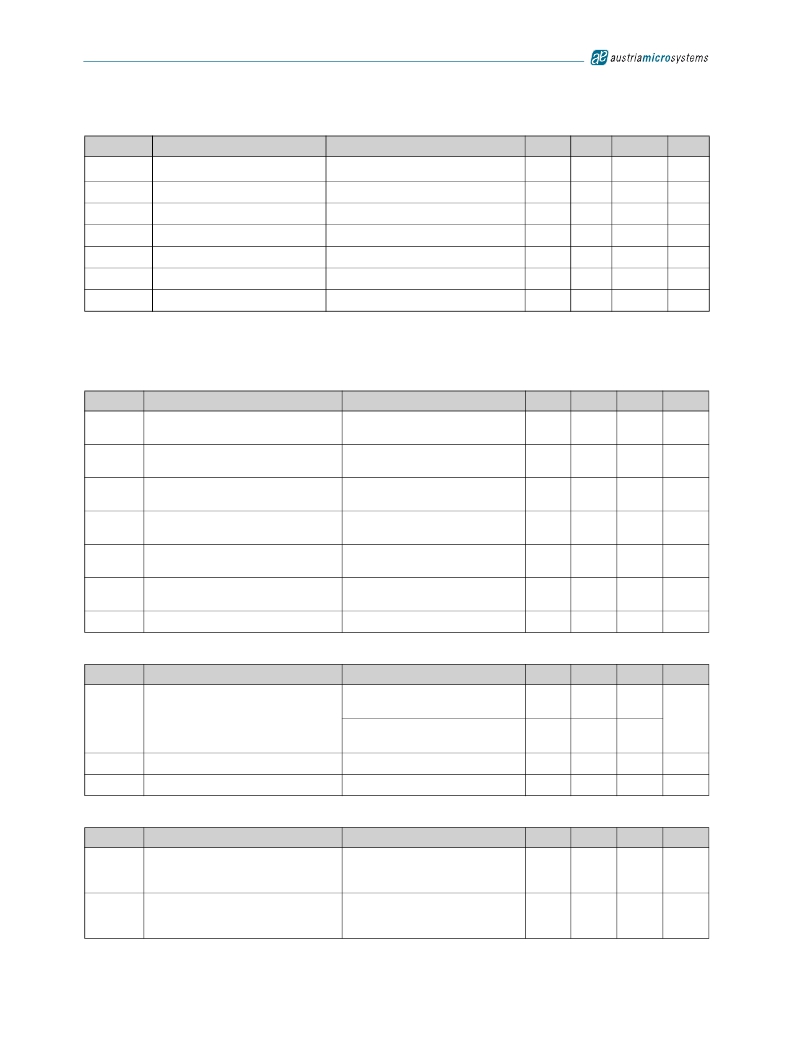
�Table� 12.� Programming� Conditions� (Continued)�
�Symbol�
�R� programmed�
�Parameter�
�Programmed� fuse� resistance� (log� 1)�
�Conditions�
�10μA� max.� current� @� 100mV�
�Min�
�100k�
�Typ�
�Max�
�∞�
�Units�
�Ω�
�R� unprogrammed� Unprogrammed� fuse� resistance� (log� 0)�
�2mA� max.� current� @� 100mV�
�50�
�100�
�Ω�
�t� PROG�
�Programming� time� per� bit�
�Time� to� prog.� a� singe� fuse� bit�
�10�
�20�
�μs�
�t� CHARGE�
�f� LOAD�
�f� READ�
�f� WRITE�
�Refresh� time� per� bit�
�LOAD� frequency�
�READ� frequency�
�WRITE� frequency�
�Time� to� charge� the� cap� after� t� PROG�
�Data� can� be� loaded� at� n*2μs�
�Read� the� data� from� the� latch�
�Write� the� data� to� the� latch�
�1�
�500�
�2.5�
�2.5�
�μs�
�kHz�
�MHz�
�MHz�
�6.5� Timing� Characteristics�
�T� AMB� =� -40� to� +150oC,� VDD5V� =� 3.0-3.6V� (3V� operation)� VDD5V� =� 4.5-5.5V� (5V� operation),� unless� otherwise� noted.�
�Table� 13.� Synchronous� Serial� Interface� (SSI)�
�Symbol�
�Parameter�
�Conditions�
�Min�
�Typ�
�Max�
�Units�
�t� DO� active�
�t� CLK� FE�
�T� CLK/2�
�t� DO� valid�
�t� DO� tristate�
�t� CSn�
�Data� output� activated� (logic� high)�
�First� data� shifted� to� output� register�
�Start� of� data� output�
�Data� output� valid�
�Data� output� tristate�
�Pulse� width� of� CSn�
�Time� between� falling� edge� of� CSn� and�
�data� output� activated�
�Time� between� falling� edge� of� CSn� and�
�first� falling� edge� of� CLK�
�Rising� edge� of� CLK� shifts� out� one� bit� at� a�
�time�
�Time� between� rising� edge� of� CLK� and�
�data� output� valid�
�After� the� last� bit� DO� changes� back� to�
�“tristate”�
�CSn� =high;� To� initiate� read-out� of� next�
�angular� position�
�500�
�500�
�500�
�100�
�413�
�100�
�ns�
�ns�
�ns�
�ns�
�ns�
�ns�
�f� CLK�
�Read-out� frequency�
�Clock� frequency� to� read� out� serial� data�
�>0�
�1�
�MHz�
�Table� 14.� Pulse� Width� Modulation� Output�
�Symbol�
�f� PWM�
�PW� MIN�
�PW� MAX�
�Parameter�
�PWM� frequency�
�Minimum� pulse� width�
�Maximum� pulse� width�
�Conditions�
�Signal� period� =� 1025μs� ±5%� at� T� amb� =�
�25oC�
�Signal� period� =1025μs� ±10%� at� T� amb� =�
�-40� to� +150oC�
�Position� 0d;� angle� 0� degree�
�Position� 1023d;� angle� 359.65� degree�
�Min�
�0.927�
�0.878�
�0.90�
�922�
�Typ�
�0.976�
�0.976�
�1�
�1024�
�Max�
�1.024�
�1.074�
�1.10�
�1126�
�Units�
�kHz�
�μs�
�μs�
�Table� 15.� Incremental� Outputs�
�Symbol�
�t� Incremental�
�outputs� valid�
�t� Dir� valid�
�Parameter�
�Incremental� outputs� valid� after� power-up�
�Directional� indication� valid�
�Conditions�
�Time� between� first� falling� edge� of� CSn�
�after� power-up� and� valid� incremental�
�outputs�
�Time� between� rising� or� falling� edge� of�
�LSB� output� and� valid� directional�
�indication�
�Min�
�Typ�
�Max�
�500�
�500�
�Units�
�ns�
�ns�
�www.austriamicrosystems.com/AS5140H�
�Revision� 1.4�
�10� -� 37�
�发布紧急采购,3分钟左右您将得到回复。
相关PDF资料
ASDMB-ADAPTER-KIT
ASDMB MEMSPEED P II OSC KIT
ASFLMPLP-ADAPTER-KIT
ASFLMPLP MEMSPEED P II OSC KIT
AT24C01-10SI-1.8
IC EEPROM 1KBIT 400KHZ 8SOIC
AT24C01B-TSU-T
IC EEPROM 1KBIT 1MHZ SOT23-5
AT24C02C-XHM-B
IC EEPROM 2KBIT 1MHZ 8TSSOP
AT24C04AN-10SI-2.7
IC EEPROM 4KBIT 400KHZ 8SOIC
AT24C08B-PU
IC EEPROM 8KBIT 1MHZ 8DIP
AT24C1024B-TH25-B
IC EEPROM 1MBIT 1MHZ 8TSSOP
相关代理商/技术参数
AS51400FLF
制造商:TT Electronics / IRC 功能描述:AS51400FLF
AS51400HLF
制造商:TT Electronics / IRC 功能描述:AS51400HLF
AS51400JLF
制造商:TT Electronics / IRC 功能描述:AS51400JLF
AS51401FLF
制造商:TT Electronics / IRC 功能描述:AS51401FLF
AS51401HLF
制造商:TT Electronics / IRC 功能描述:AS51401HLF
AS51401JLF
制造商:TT Electronics / IRC 功能描述:AS51401JLF
AS51402FLF
制造商:TT Electronics / IRC 功能描述:AS51402FLF
AS51402HLF
制造商:TT Electronics / IRC 功能描述:AS51402HLF