- 您现在的位置:买卖IC网 > Sheet目录311 > AS5140 PB (ams)BOARD PROGRAM AS5140
AS5140H
Data Sheet - E l e c t r i c a l C h a r a c t e r i s t i c s
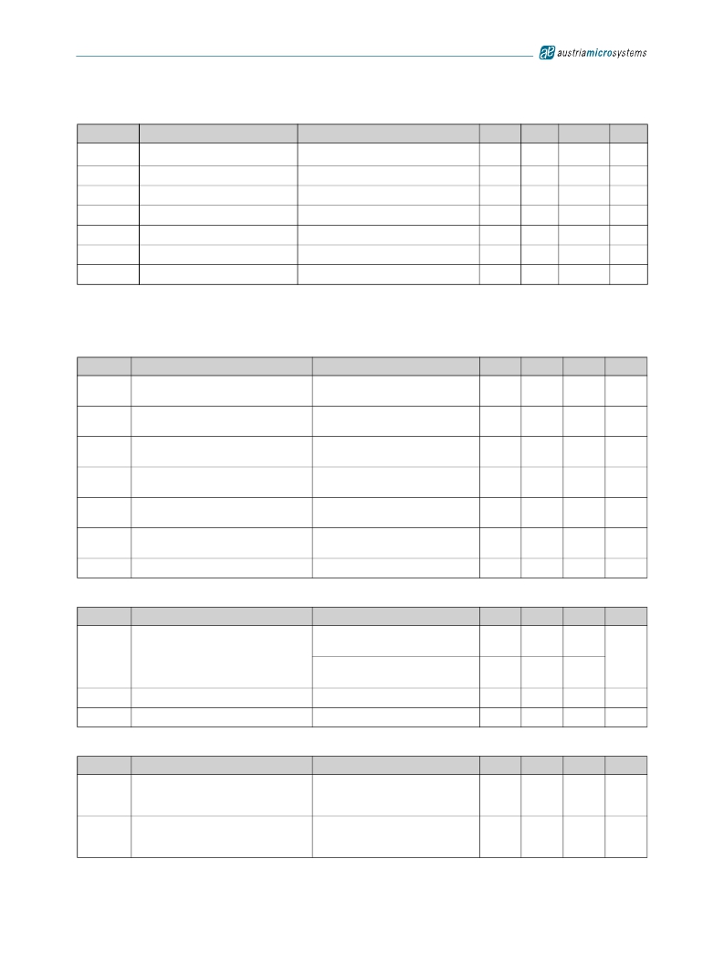
Table 12. Programming Conditions (Continued)
Symbol
R programmed
Parameter
Programmed fuse resistance (log 1)
Conditions
10μA max. current @ 100mV
Min
100k
Typ
Max
∞
Units
Ω
R unprogrammed Unprogrammed fuse resistance (log 0)
2mA max. current @ 100mV
50
100
Ω
t PROG
Programming time per bit
Time to prog. a singe fuse bit
10
20
μs
t CHARGE
f LOAD
f READ
f WRITE
Refresh time per bit
LOAD frequency
READ frequency
WRITE frequency
Time to charge the cap after t PROG
Data can be loaded at n*2μs
Read the data from the latch
Write the data to the latch
1
500
2.5
2.5
μs
kHz
MHz
MHz
6.5 Timing Characteristics
T AMB = -40 to +150oC, VDD5V = 3.0-3.6V (3V operation) VDD5V = 4.5-5.5V (5V operation), unless otherwise noted.
Table 13. Synchronous Serial Interface (SSI)
Symbol
Parameter
Conditions
Min
Typ
Max
Units
t DO active
t CLK FE
T CLK/2
t DO valid
t DO tristate
t CSn
Data output activated (logic high)
First data shifted to output register
Start of data output
Data output valid
Data output tristate
Pulse width of CSn
Time between falling edge of CSn and
data output activated
Time between falling edge of CSn and
first falling edge of CLK
Rising edge of CLK shifts out one bit at a
time
Time between rising edge of CLK and
data output valid
After the last bit DO changes back to
“tristate”
CSn =high; To initiate read-out of next
angular position
500
500
500
100
413
100
ns
ns
ns
ns
ns
ns
f CLK
Read-out frequency
Clock frequency to read out serial data
>0
1
MHz
Table 14. Pulse Width Modulation Output
Symbol
f PWM
PW MIN
PW MAX
Parameter
PWM frequency
Minimum pulse width
Maximum pulse width
Conditions
Signal period = 1025μs ±5% at T amb =
25oC
Signal period =1025μs ±10% at T amb =
-40 to +150oC
Position 0d; angle 0 degree
Position 1023d; angle 359.65 degree
Min
0.927
0.878
0.90
922
Typ
0.976
0.976
1
1024
Max
1.024
1.074
1.10
1126
Units
kHz
μs
μs
Table 15. Incremental Outputs
Symbol
t Incremental
outputs valid
t Dir valid
Parameter
Incremental outputs valid after power-up
Directional indication valid
Conditions
Time between first falling edge of CSn
after power-up and valid incremental
outputs
Time between rising or falling edge of
LSB output and valid directional
indication
Min
Typ
Max
500
500
Units
ns
ns
www.austriamicrosystems.com/AS5140H
Revision 1.4
10 - 37
发布紧急采购,3分钟左右您将得到回复。
相关PDF资料
ASDMB-ADAPTER-KIT
ASDMB MEMSPEED P II OSC KIT
ASFLMPLP-ADAPTER-KIT
ASFLMPLP MEMSPEED P II OSC KIT
AT24C01-10SI-1.8
IC EEPROM 1KBIT 400KHZ 8SOIC
AT24C01B-TSU-T
IC EEPROM 1KBIT 1MHZ SOT23-5
AT24C02C-XHM-B
IC EEPROM 2KBIT 1MHZ 8TSSOP
AT24C04AN-10SI-2.7
IC EEPROM 4KBIT 400KHZ 8SOIC
AT24C08B-PU
IC EEPROM 8KBIT 1MHZ 8DIP
AT24C1024B-TH25-B
IC EEPROM 1MBIT 1MHZ 8TSSOP
相关代理商/技术参数
AS51400FLF
制造商:TT Electronics / IRC 功能描述:AS51400FLF
AS51400HLF
制造商:TT Electronics / IRC 功能描述:AS51400HLF
AS51400JLF
制造商:TT Electronics / IRC 功能描述:AS51400JLF
AS51401FLF
制造商:TT Electronics / IRC 功能描述:AS51401FLF
AS51401HLF
制造商:TT Electronics / IRC 功能描述:AS51401HLF
AS51401JLF
制造商:TT Electronics / IRC 功能描述:AS51401JLF
AS51402FLF
制造商:TT Electronics / IRC 功能描述:AS51402FLF
AS51402HLF
制造商:TT Electronics / IRC 功能描述:AS51402HLF